
English
Views: 0 Author: Site Editor Publish Time: 2026-09-25 Origin: Site


In high-hazard industrial and marine environments, extinguishing Class B flammable liquid fires requires highly specialized, multi-stage suppression systems. Procurement engineers and facility managers often face ambiguity when specifying components for foam proportioning systems. Misunderstanding the distinct hydraulic, mechanical, and material requirements of water delivery versus foam concentrate delivery leads to catastrophic system failures, failed regulatory inspections, and severe safety liabilities. This guide breaks down the technical specifications, operational mechanics, and integration requirements of a foam transfer pump vs fire pump to ensure accurate system design and compliance.
Distinct Roles: Fire pumps deliver high-volume water at high pressure, while foam transfer pumps deliver highly viscous foam concentrate to a proportioner.
Mechanical Differences: Fire pumps utilize centrifugal force (e.g., split case, vertical turbine) to handle water velocity, whereas foam transfer pumps utilize positive displacement (gear or rotary lobe) to manage fluid viscosity.
Material Requirements: Foam concentrates are highly corrosive, necessitating specialized metallurgy like a stainless steel foam transfer pump, whereas fire pumps focus on handling fresh or saltwater.
System Integration: Both pumps must operate in precise synchronization; a mismatch in flow rates, pressure curves, or driver configurations will result in ineffective foam generation.
Defining success criteria requires isolating the specific job each pump performs within the broader suppression architecture. You cannot design a reliable suppression network without understanding these foundational roles. Each unit handles entirely different fluids under entirely different physical constraints. When a hazard event occurs, these components must activate in a precise sequence to blanket the fuel source and suppress vapor release.
This unit acts as the primary prime mover of water in the system. It draws from a static water supply like a dedicated above-ground tank, a municipal reservoir, or a marine sea chest. In some configurations, it acts as a booster pump. This raises the pressure of existing city water supplies to meet the demands of the hazard area. The unit operates continuously during an event. It must maintain baseline suppression capabilities and satisfy the total hydraulic demand for the entire sprinkler or monitor network.
The operational sequence relies heavily on this primary mover. A smaller jockey pump maintains static pressure in the piping network to prevent false alarms and water hammer. When a sprinkler head opens or a deluge valve trips, the system pressure drops rapidly. The jockey pump cannot keep up with this demand. The main controller senses the pressure drop and activates the primary water pump. If this machine fails to start or cannot reach its rated pressure, the entire suppression system collapses immediately, regardless of how much foam concentrate you have in storage.
This machine operates as a secondary, highly specialized injection mechanism. It draws raw foam concentrate from a storage bladder or an atmospheric tank. It then delivers the concentrate at a precise, elevated pressure to the proportioning equipment. Devices like balanced pressure proportioners or in-line eductors rely entirely on this steady flow. They mix the concentrate into the main water stream at exact ratios, typically 1%, 3%, or 6%.
The operational environment for this unit is highly demanding. The pump must push viscous fluid against the high pressure already created by the primary water lines. For a balanced pressure proportioning system to work, the concentrate must arrive at the proportioner at a pressure roughly 15 to 25 PSI higher than the incoming water pressure. The transfer unit runs simultaneously with the main water pump, constantly circulating concentrate. A pressure regulating valve bleeds off excess concentrate and returns it to the storage tank, ensuring the injection pressure remains perfectly balanced with the water line.
Comparing the engineering principles dictates pump selection for each fluid type. You must evaluate fluid dynamics, mechanical design, and material science to build a compliant system. Applying water-pumping logic to concentrate delivery guarantees mechanical failure.
Water presents low viscosity. It features predictable flow dynamics across various temperatures. It acts as a Newtonian fluid, meaning its viscosity remains constant regardless of the shear rate applied by an impeller. Centrifugal forces move water easily and efficiently. You can calculate friction loss in the piping using standard Hazen-Williams formulas.
Conversely, foam concentrates exhibit extremely high viscosity. This thickness often ranges from 10 to over 5,000 centipoise. They display pseudo-plastic, non-Newtonian behaviors. Their thickness heavily depends on ambient temperature and shear rate. A drop in temperature causes the concentrate to thicken dramatically. This requires significantly more torque from the motor to initiate flow. As the gears apply shear force to the fluid, it temporarily thins out, allowing it to flow through the piping. You must account for these shear-thinning traits and temperature variables during system design, often requiring oversized motors to handle cold-start conditions.
Primary water pumps rely on centrifugal force to move high volumes of fluid efficiently. An impeller spins rapidly inside a volute casing. It creates a vacuum at the impeller eye, drawing water in, and slinging it outward to build velocity and pressure. Centrifugal units do not trap specific volumes of water; they simply impart kinetic energy. Common configurations handle specific site requirements.
Horizontal Split Case: Delivers high capacity for large industrial facilities, refineries, and aircraft hangars. The casing splits horizontally for easy maintenance access to the rotating assembly.
Vertical Turbine: Ideal for drafting water vertically from underground concrete tanks, rivers, or open bodies of water where flooded suction is impossible.
End Suction: Provides a cost-effective, single-stage solution for smaller hydraulic loads and commercial buildings.
Vertical Split or In-line: Utilized frequently when mechanical room floor space is strictly limited, allowing the motor to sit directly above the pump casing.
A firefighting foam transfer pump requires positive displacement mechanics. Centrifugal impellers simply slip and cavitate when attempting to move thick fluids, generating massive amounts of heat without moving the liquid. Rotary gear, sliding vane, or rotary lobe designs trap specific volumes of fluid between the mechanical elements and the casing. They physically push this thick concentrate into the discharge pipe. This guarantees a constant flow rate regardless of fluctuating system backpressure. For every rotation of the shaft, a precise volume of concentrate moves forward.
Heavy-duty electric motors or dedicated diesel engines typically drive primary water pumps. This ensures continuous operation during catastrophic power outages. Diesel engines require dedicated fuel tanks, cooling loops, and exhaust systems, making their installation complex but highly reliable for remote sites.
A foam transfer pump offers more driver flexibility. Electric motors and diesel engines work exceptionally well for large tank farms. However, specialized water-motor drivers like Pelton wheels offer another highly reliable option. They utilize the primary water pressure to mechanically drive the concentrate unit. A stream of water hits the Pelton wheel, spinning the shaft connected to the positive displacement gears. This ensures perfectly synchronized proportioning without relying on any external electrical power. If the water flows, the concentrate flows.
Standard water pump casings typically utilize cast iron. Bronze impellers are common for basic municipal or freshwater applications. These materials provide decades of reliable service when handling clean, neutral water.
However, foam concentrates contain aggressive surfactants, salts, and solvents. The industry shift toward Synthetic Fluorine-Free Foams (SFFF) introduces even more aggressive chemical profiles. These chemicals degrade standard metals quickly. If you leave concentrate sitting in a cast iron casing for months between annual tests, the iron will rust, pit, and bind the internal gears. When the motor attempts to start, it will either trip the electrical breaker or snap the drive shaft. You must specify a stainless steel foam transfer pump using 316 SS or specialized bronze alloys. This prevents internal pitting and stops the gears from seizing during long dormant periods.
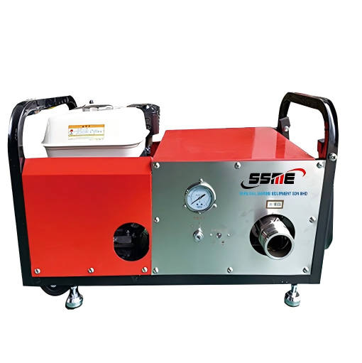
Marine and offshore environments introduce unique hazards. Pitch, roll, vibration, and continuous salt spray dictate strict equipment standards. Standard commercial pumps fail rapidly in these harsh conditions. Engineers must design systems that survive the environment long before they ever fight a fire.
A marine fire pump must utilize duplex stainless steel, nickel-aluminum bronze (NAB), or titanium internals. These materials withstand continuous exposure to highly corrosive seawater. Standard cast iron will disintegrate within months when exposed to raw ocean water. You must also manage galvanic corrosion risks carefully. Integrating different pump materials within the same piping network accelerates degradation through electrolysis. Sacrificial anodes, dielectric unions, and proper grounding techniques become mandatory during installation to protect the rotating assemblies.
Oil tankers, FPSO vessels, and offshore platforms rely critically on foam systems. Helidecks, engine rooms, and cargo decks require immediate Class B suppression to prevent catastrophic vessel loss. Space and weight constraints on vessels strictly dictate the footprint of marine firefighting equipment. Vertical in-line designs minimize deck area usage. Highly compact, skid-mounted transfer systems are often required to fit tight engine room layouts. Engineers must calculate Net Positive Suction Head (NPSH) meticulously to ensure reliable drafting from deep hull tanks, compensating for the vessel's movement in heavy seas.
Translating technical specifications into operational reliability requires careful analysis. You must evaluate sizing, compatibility, and certifications before finalizing any design. Guesswork during the procurement phase leads to failed commissioning tests.
Water pump sizing depends entirely on total system hydraulic demand. Engineers calculate the required gallons or liters per minute based on the hazard area square footage and the required application density. They also determine the necessary residual pressure at the furthest discharge nozzle. Foam pump sizing follows a different metric. It is dictated by the required proportioning ratio relative to the total water flow.
Determine the total water flow required for the hazard zone (e.g., 2,000 GPM).
Identify the proportioning ratio of your chosen concentrate (e.g., 3%).
Calculate the baseline concentrate demand (2,000 x 0.03 = 60 GPM).
Add a 10% to 15% safety margin to account for the pressure relief valve bypass back to the tank.
Select a positive displacement unit capable of delivering 70 GPM at the required overpressure.
Evaluating pump curves ensures system harmony. The transfer unit must deliver concentrate at a higher pressure than the main water line. It typically needs to be 15 to 25 PSI higher than the primary water pressure at the proportioner. If the pressures match, the concentrate will not inject properly into the water stream. Engineers use mechanical pressure relief valves or variable speed drives. These devices manage excess concentrate flow effectively, routing it back to the atmospheric storage tank to prevent over-pressurization of the injection lines.
Compliance ensures legal protection and operational safety. Equipment must meet strict international codes. Insurance underwriters will reject installations that lack proper documentation.
Water pumps must meet NFPA 20 standards. They require strict UL listing and FM approval for commercial use.
Foam pumps must adhere to NFPA 11 standards. This covers low, medium, and high-expansion systems and mandates positive displacement technology.
Marine installations demand specific maritime certifications. ABS, DNV, or USCG type approvals are mandatory for offshore installations, requiring rigorous factory witness testing.
Specification | Primary Water Pump | Concentrate Transfer Pump |
|---|---|---|
Primary Fluid | Freshwater or Seawater | High-Viscosity Concentrate |
Pump Mechanics | Centrifugal (Split Case, Turbine) | Positive Displacement (Gear, Lobe) |
Material Focus | Cast Iron, Bronze, NAB | 316 Stainless Steel, Special Alloys |
Sizing Metric | Total Hydraulic Demand (GPM/LPM) | Proportioning Ratio (1%, 3%, 6%) |
Key Standard | NFPA 20 | NFPA 11 |
Addressing the realities of installation, testing, and long-term ownership prevents catastrophic failures during an actual emergency. Proper commissioning separates reliable systems from expensive liabilities.
Viscous fluids are highly susceptible to cavitation. This occurs if suction lines are undersized, too long, or exposed to cold temperatures. When the pump pulls a vacuum harder than the fluid can flow, bubbles form and collapse violently. Cavitation sounds like marbles rattling inside the casing. It destroys gear teeth rapidly. You can mitigate this by designing flooded suction configurations. Place the atmospheric tank directly above the pump inlet. Minimizing elbows, valves, and restrictions in the suction piping prevents dangerous pressure drops. Always ensure the Net Positive Suction Head available (NPSHa) exceeds the pump's required NPSHr by at least 3 to 5 feet.
Facilities face the severe risk of concentrate drying and crystallizing. This happens inside the casing during dormant periods. It glues the internal gears together. Implement strict flushing protocols to mitigate this risk. Install a dedicated clean water line tied into the suction piping for post-activation flushing. Utilize water-testing bypass loops during annual NFPA inspections. This verifies mechanical performance without wasting expensive suppression agents or discharging harmful chemicals into the environment.
Common Symptom | Potential Cause | Mitigation Strategy |
|---|---|---|
Loud rattling noise during operation | Cavitation due to restricted suction line | Increase suction pipe diameter; remove unnecessary elbows. |
Motor trips breaker on startup | Gears seized from crystallized concentrate | Implement post-test clean water flushing protocols. |
Insufficient foam generation at nozzle | Transfer pressure lower than water pressure | Adjust pressure relief valve to maintain 15-25 PSI differential. |
Rapid casing corrosion | Incompatible metallurgy with SFFF agents | Upgrade to 316L stainless steel internals. |
Evaluate suppliers based on their ability to provide integrated skid packages. A complete package includes the pump, motor, controller, and relief valves pre-piped on a single base. Avoid sourcing isolated components from different vendors, as this leads to integration failures and finger-pointing during commissioning. When selecting a marine fire pump supplier, check specific criteria. Look for the immediate availability of OEM replacement parts. Ensure they maintain global service networks for vessels docking internationally. Verify their testing facilities meet ABS or DNV testing protocols, allowing for full-load factory acceptance testing before shipment.
A primary water pump and a concentrate transfer pump are not interchangeable. They act as highly specialized, interdependent components of a complete Class B suppression system. Base water pump selection on total hydraulic demand, footprint constraints, and your specific water source. Base transfer pump selection on fluid viscosity, proportioning ratio, and extreme corrosion resistance.
Audit your current hazard classifications to confirm the exact required suppression agents and proportioning ratios.
Consult a certified fire protection engineer to calculate exact hydraulic demands and necessary overpressure margins.
Design a dedicated clean-water flushing loop into the piping architecture to ensure long-term mechanical reliability.
Request certified performance curves and viscosity correction charts from manufacturers before finalizing procurement.
A: No. Centrifugal pumps fail to move high-viscosity fluids efficiently. They lose pressure and flow capacity as fluid thickness increases. Positive displacement pumps are required to push thick concentrate consistently against system backpressure.
A: Concentrates contain highly corrosive surfactants and salts. You should specify 316 stainless steel or specialized bronze alloys. These materials resist internal pitting and prevent the internal gears from seizing during long periods of inactivity.
A: Common types include Horizontal Split Case for high capacity, Vertical Turbine for drafting from underground tanks, End Suction for smaller loads, and Vertical In-line pumps. The latter is ideal when mechanical room floor space is highly restricted.
A: You size it based on the required proportioning percentage. If the system requires a 3% ratio and the primary unit delivers 1,000 GPM of water, the transfer unit must deliver exactly 30 GPM of concentrate at a higher pressure.
A: NFPA 11 governs these systems. It requires transfer units to utilize positive displacement mechanics. They must possess run-dry capabilities for a limited time and deliver precise flow rates to ensure accurate proportioning.
A: Offshore platforms face severe saltwater corrosion, extreme vibration, and strict space limits. Specialized units use nickel-aluminum bronze or duplex stainless steel. They feature space-saving vertical designs and hold mandatory marine classification society approvals like ABS or DNV.


